


Low Energy Inverse Photoelectron Spectroscopy
Low Energy Inverse Photoelectron Spectroscopy
LEIPS
KEY FEATURES of Low Energy Inverse Photoelectron Spectroscopy (LEIPS)*
-
Obtain information on the unoccupied electronic energy levels
-
Measurement of electron affinity of the sample
-
Low damage analysis of organic materials
-
Measurement at same location of XPS and UPS
Principle of LEIPS
An energy diagram of a semiconductor sample measurement by LEIPS and UPS is shown in Figure 1. UPS provides information about the occupied energy levels of the valence band by analyzing the photoelectrons (e-) emitted from the sample during irradiation by ultraviolet light (hν). LEIPS reverses the role of light and electrons as it measures the near-ultraviolet light (hν) emitted from a sample during electron (e-) bombardment. LEIPS provides information about the unoccupied levels of the conduction band and enables direct measurement of the electron affinity of the sample.
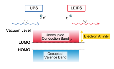
Figure 1. UPS and LEIPS energy diagram
Features of ULVAC-PHI LEIPS
Inverse photoelectron spectroscopy (IPES) measures light generated by irradiating a sample with electrons. LEIPS is very different from conventional IPES and measures near ultraviolet light using low energy electrons of 5 eV or less. For this reason, electron beam damage to organic samples is dramatically reduced. The low energy electron beam is set to a fixed energy and the sample bias is adjusted to sweep the net energy of the bombarding electrons. Generated ultraviolet light of 5 eV or less is selected by a band pass filter on the atmosphere side of the belljar and detected with a photomultiplier tube. A plot is then generated of the photon signal intensity (at a fixed energy band pass filter on the detector) vs. net kinetic energy of the bombarding electrons. Since the photodetector is located outside the belljar, it is easy to select the light energy by replacing the band pass filter.
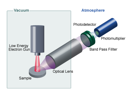
Figure 2. Schematic of LEIPS analysis setup
Measurement of electron affinity by LEIPS
In LEIPS, the energy (hν) of the detected photons can be changed by changing the band pass filter of the photodetector. When plotting the rising (onset) energy against the band pass energy for each filter, there is a linear correlation, and extrapolation of the line to zero kinetic energy of the bombarding electron yields the electron affinity, as shown in Figure 3. Obtaining the electron affinity is difficult with conventional IPES.
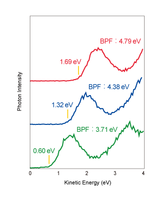
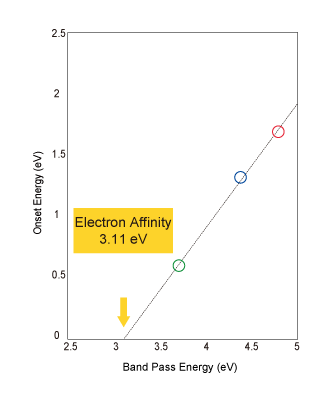
Figure 3. (left) LEIPS spectrum of copper phthalocyanine thin film sample (10 nm film on ITO) measured with 3 different band pass filters (BPF)
(right) Plot of the rising (onset) energy of the LEIPS spectrum vs. the band pass filter energy. Extrapolating to zero onset energy yields the electron affinity.
Sample provided by: Organic Optoelectronics Practical Development Center(i3-opera)
Low damage analysis of organic materials
A comparison of the degree of electron beam damage on a thin film C60 sample using LEIPS electron energies and conventional IPES energies is shown in Figure 4. When the sample was irradiated with 10 eV electrons, equivalent to conventional IPES, the spectral shape changed, indicating that electronic damage had occurred. On the other hand, in the LEIPS measurement using 5 eV of electron energy, there is no change in the spectrum after extensive measurement time, suggesting that no sample damage has occurred.
LEIPS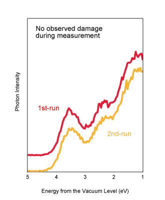
Conventional IPES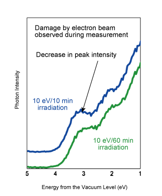
Figure 4. LEIPS spectrum of a C60 thin film sample measured at an electron energy of: (left) less than 5 eV with LEIPS, (right) 10 eV, similar to conventional IPES
Sample provided by: Organic Optoelectronics Practical Development Center(i3-opera)
Analysis example
Measurement of both the occupied and unoccupied electronic energy levels of a sample
From the energy of the occupied (valence) level obtained by UPS and the energy of the unoccupied (conduction) level obtained by LEIPS, the whole picture of the band structure can be understood (Figure 5). By combining these two complementary techniques, LEIPS and UPS, it is possible to know the level of both electrons and vacancies in a semiconductor sample. In addition, the ionization potential can be obtained from the highest occupied molecular orbital (HOMO) of the UPS measurement, and electron affinity can be obtained from the lowest unoccupied molecular orbital (LUMO) of the LEIPS measurement. From the difference in those two values, the semiconductor band gap energy can be calculated.
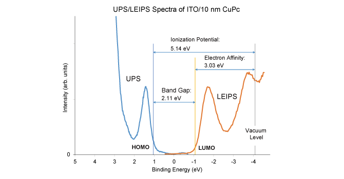
Figure 5. LEIPS and UPS spectra of copper phthalocyanine thin film sample
Measurement at the same location for LEIPS, XPS, and UPS
In the VersaProbe 4, LEIPS, UPS, Argon and GCIB ion beams, and neutralization beams are all aligned to the XPS measurement position. This allows for comprehensive evaluation of organic semiconductor materials.
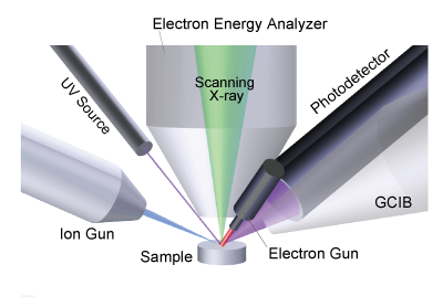
Figure 6. Schematic diagram around sample
Comparison Table
| Item | ULVAC-PHI LEIPS | Conventional inverse photoemission spectroscopy |
| Measurement position of sample | Same location as XPS, UPS Ar gun, GCIB gun can also irradiate the same position |
Different position from XPS, UPS Sample transport required before and after measurement |
| Energy of electrons | 5 eV or less Low damage to organic materials |
~ 10 eV Increased damage to organic materials |
| Energy selection | Can exchange band pass filter outside the belljar | Band pass filter is in ultra-high vacuum chamber and difficult to replace |
| Energy resolution | 0.45 eV or less | ~ 0.6 eV |